Recovered steel shot is not separated reliably by its grade name alone. You need to match the screen opening to the required sieve distribution, control how the material travels across the deck, and verify each collected fraction before returning it to production.
Key takeaways
- Treat SAE J444 grades as sieve distributions, not single particle diameters.
- Match screen openings to the target shot fractions and collection bins.
- Control feed rate, deck loading, and moisture to protect separation accuracy.
- Verify every fraction with representative samples and recorded sieve results.
What actually gets separated: shot grade, size distribution, and contamination
SAE J444 designations such as S70, S230, and S930 describe a sieve-based particle-size distribution, not one exact particle diameter. A steel shot grade is nominal; the usable specification comes from the percentages retained on, and passing through, each stated test sieve.
1. Set the screen against the required retained and passing fractions, not the grade label alone. A particle can pass an aperture when its orientation allows it, while an elongated or fractured piece can remain on it.
Specify the opening in millimetres or micrometres and name the test-sieve standard, because mesh count alone ignores wire diameter.
2. Treat contamination as a separate control problem. A requirement such as broken shot separation A75?? needs clarification, because broken shot, dust, rust scale, spent abrasive, and foreign ferrous pieces can share the target size range. Oil, coolant, moisture, and scale can also bind fines to the deck or each other and distort the fractions.
3. Do not infer shape from size. Rounded steel shot and angular steel grit can occupy the same sieve range and leave the screen in the same fraction. Inspect shape and fracture behaviour separately through visual or microscopic checks, hardness controls, magnetic separation, and dust removal.
How screen decks turn one mixed feed into separate abrasive fractions
An even feed lands on a vibrating screen deck, where controlled motion spreads the abrasive into a shallow bed. Vibration stratifies that bed: smaller particles move toward the screen surface, pass through the selected opening, and collect below; larger particles travel onward as oversize.
Specify the opening, not mesh count alone. The screen aperture depends on both the clear gap and the wire diameter, so two screens with the same mesh count can produce different cuts. Put the opening in millimetres or micrometres on the purchase specification and name the test-sieve standard used to verify it.
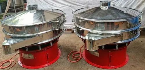
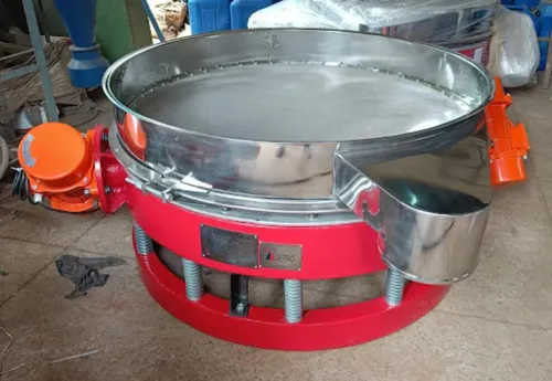
A single-deck screening machine lens is straightforward: one deck makes one principal cut, separating oversize from material that passes. The actual cut is a distribution, not a perfect diameter boundary; spherical shot, angular grit, fractured pieces, and elongated particles can behave differently at the same nominal size.
| Arrangement | Deck layout | Output |
|---|---|---|
| Single deck | One specified opening | Oversize and passing fraction |
| Multi-deck | Coarsest screen above progressively finer screens | Oversize, intermediate fraction, and fines in one pass |
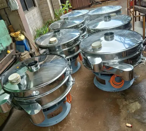
The upper deck removes coarse material first. Material passing it reaches the lower decks, where each finer screen makes another separation. This arrangement reduces repeat handling when you need several abrasive fractions, but every deck requires an identified aperture and a separate outlet.
How vibration, loading, and material condition change separation accuracy
Set the operating window by watching bed depth and product carryover, not by turning up vibration. Vibration amplitude and frequency must move particles across the deck without launching them; excessive acceleration causes bouncing and coarse carryover, while insufficient motion creates buildup and blinding.
Adjust deck inclination, feed rate and residence time together: a steeper deck shortens residence time, while a longer, slower path gives particles more exposure to the apertures.
1. Prepare a dry, free-flowing feed. Remove tramp metal before screening; use magnetic separation for ferrous fragments, and add aspiration or dust removal when fine debris could pass through the same opening as usable shot.
2. Spread the feed evenly across the deck and keep the bed shallow. Overload creates a deep bed that blocks fines from the apertures, sending coarse material into the undersize stream. Correct the feed rate before increasing amplitude.
3. Raise amplitude or frequency only until the material advances consistently. Excessive motion increases bounce and carryover; too little motion causes accumulation. Use deck inclination and residence time to correct travel rather than relying on amplitude alone.
4. Check the failure signature. Fines blinding reduces open area and raises retained fines. Wet or oily shot forms agglomerates, leaving coarse contamination in the fines. Worn shot appears as an increased fines load or a shifted retained distribution.
Sample each outlet separately. Screening cannot remove every risk: keep dust, rust scale, and broken machine parts out through dry-feed preparation, magnetic separation, and dust removal where required.
A practical operating sequence for clean, separate collection
Begin the operating sequence by inspecting the deck, measuring the actual openings, and checking the test-sieve specification against the required cut. A screen can look intact while abrasion at the feed impact zone has enlarged apertures and shifted the size distribution.
- Remove adhered fines, oil, moisture, and rust scale; confirm the screen-cleaning devices work.
- Examine the cloth at the feed impact zone for thinning, broken wires, and stretched openings.
- Remove tramp metal with magnetic separation where ferrous fragments could contaminate recovered shot.
- Start the screen and allow it to reach stable motion before opening the feed.
- Spread the material across the full deck width and keep the bed shallow; overfeeding sends coarse particles into the undersize stream.
- Keep every outlet and hopper separate, then inspect both oversize and undersize streams rather than judging only the reusable fraction.
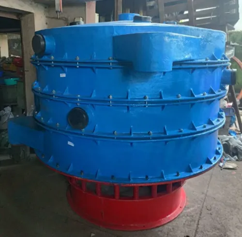
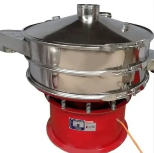
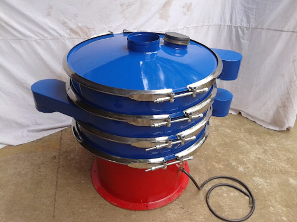
A multi-deck vibrating separator places the coarsest opening on the upper deck and finer openings below it. This arrangement produces several fractions in one pass, but only if each discharge remains isolated.
Compare equipment using these criteria:
| Criterion | What to confirm | Why it matters |
|---|---|---|
| Deck area | Area matched to feed rate and target bed depth | Prevents overload and misplaced particles |
| Number of decks | One cut or several progressive cuts | Determines fraction count |
| Screen cleaning | Balls, sliders, brushes, or another provision | Limits blinding |
| Feed control | Adjustable, evenly distributed feed | Improves separation stability |
| Inspection access | Direct view and aperture measurement access | Exposes wear before product drift |
| Outlets | Separate, sealed discharge paths | Prevents fraction mixing |
At this decision point, Separation Engineers (India) can be considered when you specify the cut, feed rate, fraction count, and contamination controls—not merely a grade name.
Related product
 | Steel Shot Screening Machine The Paint Filtration Screening Machine from Separation Engineers India is a high-performance solution designed to ensure smooth, impurity-free... View product → |
How to prove that each abrasive fraction meets its acceptance range
A representative sampling plan starts at the moving product stream, not with material sitting on the screen. Take increments during discharge, or collect samples from several points in the batch; one scoop from a segregated hopper can make a poorly graded lot appear compliant. Weigh the combined sample before testing.
Run it through a calibrated sieve stack with openings matching the specified cut. Record the mass retained on every sieve and in the pan, then calculate each retained-mass percentage as retained mass divided by total sample mass, multiplied by 100.
| Fraction | Calculation | Acceptance decision |
|---|---|---|
| Oversize | Mass above the upper specified cut ÷ total mass × 100 | Must remain below the written maximum |
| Usable fraction | Mass between the specified lower and upper cuts ÷ total mass × 100 | Must fall inside the written acceptance range |
| Fines | Mass below the lower cut and in the pan ÷ total mass × 100 | Must remain below the written maximum |
| Contamination | Separately identified broken shot, rust scale, dust, oil, or foreign material | Must remain below the stated contamination limit |
Keep the results with the batch number, sample mass, sieve identification, test date, and operator record. If a result drifts outside the acceptance range, check feed loading and bed depth, moisture or oil, deck wear, actual aperture measurement, and vibration settings before changing the nominal grade or blending fractions back together.
A passing hopper sample cannot correct a failed product stream.
Frequently asked questions
What does a steel shot grade describe?
A grade such as S70, S230, or S930 describes a sieve-based particle-size distribution. It is defined by the percentages retained on and passing through specified test sieves, not one exact diameter.
How does a screening machine separate mixed steel shot?
A vibrating screen moves the mixed feed across decks with selected openings. Smaller particles pass through each deck while larger particles continue onward, creating separate abrasive fractions.
What reduces steel shot separation accuracy?
Excessive feed rate, overloaded screen decks, uneven distribution, worn screen openings, moisture, oil, and deformed or contaminated media can reduce accuracy.
How do you verify that a steel shot fraction meets its acceptance range?
Take a representative sample, test it with the specified sieve stack, record the mass retained on each sieve, and compare the percentages with the grade's acceptance limits.