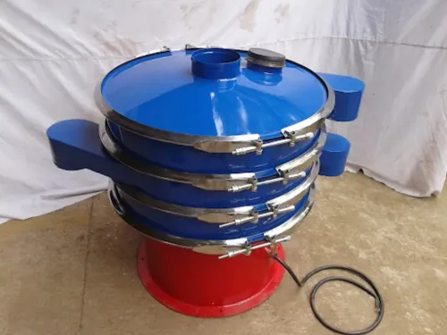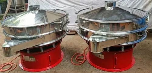
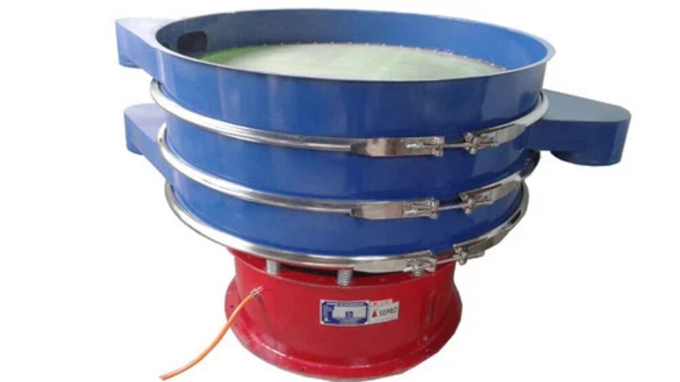
Accurate grading depends on more than choosing a screen with the right nominal aperture. You need to match the screen geometry, motion, loading conditions, and material behaviour, then verify the result with mass-balance data rather than relying on a throughput claim alone.
Key takeaways
- Use screen apertures matched to the required cut size.
- Control bed depth, feed rate, moisture, and vibration together.
- Check screen tension, deck slope, and feed distribution before testing.
- Verify accuracy by reconciling feed, oversize, undersize, and rejects.
How vibration turns a mixed feed into separated fractions
A vibratory grading machine separates a mixed feed by spreading particles across a screen, stratifying the bed, and giving undersize particles repeated chances to pass through the apertures. The vibration lifts and advances the material; larger particles migrate upward while smaller particles percolate downward toward the screen surface.
A thick, uneven feed layer reduces accuracy because particles cannot reach the openings before discharge.
- Distribute the feed across the usable screen width. A concentrated stream overloads one area while leaving the rest idle.
- Set vibration so the bed travels forward without skipping across the apertures. Each particle needs enough residence time for undersize material to find an opening.
- Let particles smaller than the aperture pass to the undersize outlet while larger particles continue to the oversize outlet. Near-size particles require more opportunities and are the main source of misplaced material.
The practical distinction is grading versus screening versus sieving versus sizing versus classification versus filtration:
| Term | Meaning | When it applies |
|---|---|---|
| Grading | Dividing solids into specified size ranges | Producing controlled fractions such as fine, medium, and coarse |
| Screening | Separating solids through a fixed-aperture screen | Industrial continuous separation |
| Sieving | Separating particles with sieves, often in laboratory testing | Measuring particle-size distribution, including ASTM C136/C136M work |
| Sizing | Assigning or separating material by particle size | General engineering language |
| Classification | Separating by size, density, shape, or settling behaviour | Air classifiers or other non-screen methods |
| Filtration | Holding solids while a liquid or gas passes through a medium | Fluid-solid separation, not ordinary dry screening |
How to specify the screen, decks, and motion for your cut size
Choose the cut from particle behaviour, not machine speed: specify the screen aperture, deck layout, and motion as one system. A screen aperture slightly larger than the target particle size improves passage, but lets oversize through if shape matters.
Mesh size alone is insufficient because wire diameter changes the open-area percentage; make the open-area percentage explicit and record the aperture geometry.
- Use square openings for a tighter size cut; use slots when elongated particles must pass, but check that needles or flakes cannot bridge the intended limit.
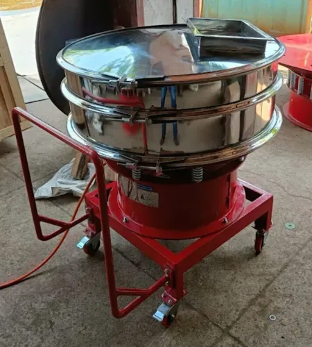
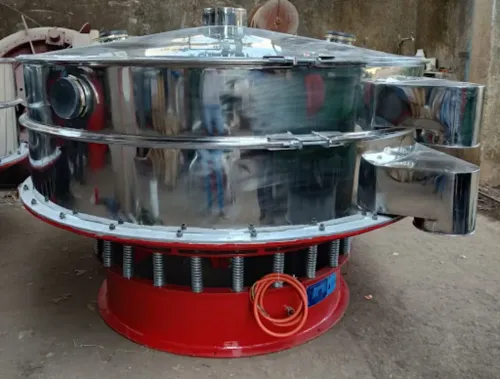
- Put the largest opening on the upper deck and progressively smaller openings below it. Size each deck for its own loading, blinding risk, wear, and discharge capacity.
- Increase screen area when feed rate or near-size content rises; do not justify capacity in tonnes per hour without stating bulk density, particle-size distribution, moisture, and open area.
- Set frequency and amplitude high enough to stratify and expose particles to openings, then reduce them if particles bounce across the deck or fines discharge with oversize.
- Increase inclination for flow and throughput; reduce it when the cut needs longer residence time and more opportunities to pass. A steep deck can move material faster while making separation worse.
- Check feed depth: a thin, even layer separates better than a deep bed. Keep feed rate below the point where openings become buried.
Laboratory sieve data, including ASTM C136/C136M results, needs pilot confirmation because production screening has moving beds and finite residence time.
For a meaningful specification, give Separation Engineers (India) the target cut, feed rate, density, moisture, aperture geometry, open-area percentage, frequency, amplitude, and deck inclination.
| Screen choice | Separation effect | Main risk |
|---|---|---|
| Square opening | Sharper size cut | Lower passage for elongated particles |
| Slotted opening | Higher passage of long particles | Needle-shaped oversize passes |
| Multiple decks | Removes coarse material early | Uneven loading between decks |
Related products
Vibrating Screening Machines The Industrial Vibro Sifter by Separation Engineers India is a high-performance vibrating screening machine designed for efficient particle... View product → |
Vibrating Screening Machines Metal Powder Vibrating Screening Machine The Metal Powder Vibrating Screening Machine by Separation Engineers India is a high-performance screening solution designed for precise and... View product → |
How material behaviour changes capacity and separation accuracy
Material behaviour changes both usable capacity and the actual cut point. A capacity calculation must use bulk density, not tonnes per hour alone: low-density feed creates a deeper layer at the same mass rate, while high-density feed can overload the deck by mass.
Particle shape also matters; flat or elongated pieces may pass only when correctly oriented.
Moisture binds fines, and temperature effects on screening appear when heat softens waxes, fats, or binders, or dries feed enough to increase dust and static charge. Static charge makes fines cling to wires and larger particles, reducing open area. Stickiness produces the same result through adhesion rather than electrical attraction.
Watch these failure modes:
- Contamination such as oil, fibres, tramp metal, or excess fines coats the deck and causes blinding, where openings are covered.
- Damp, soft, or irregular particles cause pegging, where particles lodge in apertures and block them.
- A thick bed hides openings from smaller particles; increasing feed rate then reduces recovery even before the motor reaches its load limit.
- Near-size material creates the largest cut-point error. An undersize particle can remain in the oversize stream when residence time is short, while an oversize particle can pass if its orientation permits it.
Flatter screening gives near-size particles more opportunities to pass; steeper operation raises capacity but shortens residence time. Recheck the cut after every change to moisture, temperature, feed depth, or composition.
How to set up the machine before judging its performance
Set the machine in a controlled sequence, then judge separation only after the feed, motion, and collection system reach steady operation.
1. Inspect each deck, clamp, support bar, and discharge outlet. On multi-deck machines, confirm the largest opening is on the upper deck and smaller openings follow below it.
2. Check screen tension across the full deck, not at one edge. Under-tensioned cloth can flutter and blind; excessive or uneven tension can damage the cloth or clamps.
3. Run the empty machine and record the vibration settings. Confirm whether the supplier specifies peak amplitude, peak-to-peak amplitude, or RMS vibration; confusing them can double the apparent stroke. Calculate Gamma dimensionless acceleration with Γ = A(2πf)²/g, using peak displacement A.
4. Set the inclination and vibration settings to the approved starting values before adding material. Change one setting at a time so you can identify its effect.
5. Start the feeder at a low rate and establish even feed distribution across the usable screen width. Concentrated feed creates local deck loading, a thick bed, and poor separation.
6. Add material gradually until the operating bed depth is stable. Watch for carryover, blinding, and overloaded outlets rather than judging capacity from motor sound.
7. Arrange discharge collection so every deck fraction enters a separate, labelled container without splash, bounce, or cross-contamination.
8. Begin sampling only after steady flow is established. Take operating samples from each discharge at timed intervals, excluding startup material, and record feed rate, settings, and peak amplitude with each sample.
How to prove separation accuracy with a mass balance
A clean undersize sample does not prove accurate grading. Saleable material lost to oversize can leave product purity high while recovery is poor, so measure the feed, oversize, and undersize together.
1. Take representative sampling during steady operation. Collect timed increments across the full discharge width from the feed, oversize, and undersize streams, then combine and reduce them consistently. Record total masses and check the balance: feed mass should closely equal oversize mass plus undersize mass. Investigate unexplained loss before accepting the result.
2. Perform sieve analysis on each composite sample using ASTM C136/C136M as the laboratory method. Report retained-mass percentages by size fraction, not only the percentage passing the target sieve.
Throughput is production mass per unit time; recovery is the percentage of desired feed material captured in its intended product; product purity is the percentage of that product that meets the desired size specification.
3. Treat separation efficiency as the machine’s ability to place particles in the correct outlets, using recovery and contamination together rather than substituting one for the other. Run a cut-point check with material near the target aperture, because near-size particles expose misplaced material more clearly than an easy, widely separated feed.
4. Repeat the same sampling and calculations at least three times under stable settings. Accept the result only when recovery, purity, retained-mass percentages, and throughput remain within your agreed limits. Repeat after inspecting screen wear: enlarged openings and damaged sections can shift the cut point without any change to the controls.
Frequently asked questions
How does vibration separate mixed material into fractions?
Vibration spreads and stratifies the feed, allowing smaller particles to percolate through screen apertures while larger particles remain above them.
How do you specify a vibratory grading machine for a target cut size?
Specify the cut size, screen aperture, number of decks, deck area, feed rate, and required motion so the machine matches the separation task.
Which material properties affect grading capacity and accuracy?
Particle size distribution, shape, bulk density, moisture, cohesion, temperature, and feed rate affect how quickly and accurately material passes through the screen.
How can you verify vibratory grading performance?
Collect and weigh the feed, each product fraction, and rejects, then reconcile the totals with a mass balance and test samples from each stream.
Related products
 | Vibro Shifter Industrial Vibro Shifter With Inclined Conveyor The Flour Sieving Machine by Separation Engineers India is a high-performance industrial sieving solution designed for efficient separation and... View product → |
Vibrating Screening Machines The Glass Screening Machine by Separation Engineers India is an advanced vibrating screening solution designed for precise separation and grading of... View product → |
 | Vibrating Screening Machines The Sifter Sieving Machine by Separation Engineers India is a high-performance equipment designed for precise and efficient separation of powders,... View product → |